-
09-21-2025, 03:35 PM
#361
Getting the radiator ready for final installation
Hey Y'All,
This past weekend I devoted most of my garage time towards prepping my radiator for final installation. I decided to paint it black for a more authentic look, and I chose Eastwood's Radiator paint for the task...
Scuffing, degreasing, and metal cleaning resulted in a decent prep for the paint, and it laid out well from the spray cans. I got most of the coverage with one can, but got an extra for the final coating (and just in case touchups ") ) It was good that I planned ahead for mistakes...'cause I had my wire retainers slip off while trying to unhook them from my painting frame. The radiator bounced off a towel on the concrete floor and revealed a minor scuff on the bottom flange and both hose fittings had dents
) It was good that I planned ahead for mistakes...'cause I had my wire retainers slip off while trying to unhook them from my painting frame. The radiator bounced off a towel on the concrete floor and revealed a minor scuff on the bottom flange and both hose fittings had dents  I don't think I cracked it, but wowsers, that is some soft aluminum!
I could bend the flanges straight with just finger pressure and I managed to reshape the hose fittings to nearly round again with a wooden dowel. I hope it is alright...we'll see...
Anyway, here's the pictures right before I took it off of the painting frame radiator painted black1.jpg radiator painted black2.jpg
Lastly, I trimmed up the bottom edge of my fan shroud, and then scuffed and cleaned it before adding the riv-nuts for the fan assembly. Here's a picture before it goes off for powder coating radiator shroud ready for powder coating.jpg
Until next time, Happy Building!
Craig C
Last edited by cc2Arider; 09-21-2025 at 03:42 PM.
Reason: added and edited pictures
-
09-23-2025, 07:49 AM
#362
Question about Power steering hose routing
Hey Y'All,
I wanted to check the fitment of the FFR-provided power steering hoses, and this is what I came up with 20250922_162036.jpg20250922_162042.jpg
Is this the "typical" routing? I've heard great things about the Breeze power steering hose kit. Does that route much different?
Let me know what you think 
Craig C
-
09-28-2025, 04:00 PM
#363
I decided to make my own Power Steering hoses
Hey Y'All,
No feedback about the FFR-provided Power Steering hoses...so I decided to make my own! I chose Earl's products, 'cause they're good stuff 
I got 6' of their PS reinforced and fabric covered hose ('cause I don't like the braided SS look), steel fittings, etc. I also chose to replace the low-pressure barb fitting on the fluid tank because I might decide to add a cooler later, and I think having AN fittings at both ends will be easier to design for this...
I also decided to route this as I interpreted the FFR-supplied hose (as in my previous post). Here's how it turned out
made my own PS lines1.jpg
Here's an overhead perspective
made my own PS lines2.jpg
Lastly, an image which shows that I have good clearance to the steering shaft
made my own PS lines3.jpg
For a 1st-time effort, I'm pretty "chuffed" how it turned out 
The FFR-provided 16.5 fitting did not have an o-ring (I think it was simply an inverted flare), so I ordered one of those with an o-ring that I'll install later to the pressure-side of the pump...
Until next time, Happy Building!
Craig C
Last edited by cc2Arider; 09-28-2025 at 04:02 PM.
-
09-28-2025, 04:32 PM
#364
Confirming & topping up fluids
Hey Y'All,
The reason for me adding power steering hoses was so that I could top up the fluid reservoir to prepare for cranking the engine 
Along with the aforementioned power steering system, I also checked the drivetrain fluid levels. Interestingly enough, just as MANY others have observed, the IRS came pre-filled with what appeared to be the correct volume of fluid...it just didn't reach the bottom of the fill plug (which is how most measure the system). No worries, I added fresh FORD products from a local Dealer, including the "friction modifier" for the limited slip pack. What's really strange is that Summit did not want to ship the products to me at my home address...must have some potent chemicals or something
Here's a picture for those who might want to compare their own experience to mine amount of IRS fluid shipped with unit.jpg
Next, Forte' sent me 3 qts of the Penzoil Synchromesh fluid for the TKX they sent to me...and wouldn't you know it...that, too seemed like the correct amount of fluid...but just as before, the level did not reach the bottom of the fill plug, so I got another quart and squeezed some more in. It didn't take much more. I did take advantage of my handbrake cover plate to fill up the transmission...but in all reality, I don't think I'll use it in-service in the future -- there seems to be enough room in the tunnel to sneak a fill tube in there... benefit to having the handbrake panel removeable.jpg
Lastly, I've heard about the "Garden Sprayer" oil priming method, and I thought I'd try it. It worked well. Here's a picture of the setup
alternative way to prime the oiling system.jpg
I simply pumped up the sprayer unit about 20 pumps and then hand-rotated the engine with a socket wrench on the front pulley. I then watched (and listened) for oil coming up the pushrods
The total volume for my 7" Champ pan on a DART 427W was 8 quarts.
Sometime this coming week, I plan to complete the cooling system and add Evans waterless coolant...
So until next post, Happy Building!
Craig C
-
09-28-2025, 05:09 PM
#365
Radiator installation - post1
Hey Y'All,
In my last 2 posts for this weekend, I'm highlighting how my radiator installation turned out.
First up, a before-installation picture of the painted radiator, powder-coated shroud, and installed "more airflow" fan
fan and shroud attached to painted radiator.jpg
Next up, the mocked into place Breeze "chin strap" lower radiator mount (what a great nickname!)
chin strap lower radiator support.jpg
Lastly, 2 images of the clearance you can expect when angling the radiator to 58 deg per the instructions
rad clearance on driver side.jpg rad clearance on passenger side.jpg
More pictures in post2, next...
-
09-28-2025, 05:19 PM
#366
Radiator installation - post2
Hey Y'All,
In my last post of the weekend, some details and overall imagery of my radiator installation...
An idea for returning to measured offset using zip-ties as an indexing tool. This might also be beneficial for final installation if the straps ever get loose and slip down in-use
passenger side radiator chin strap detail.jpg driver side radiator chin strap detail.jpg
Front installed picture. Note the inevitable "angled" look due to the orientation of the top radiator frame tube. It's not too bad looking
installed radiator - front view.jpg
Lastly, a view of the shroud, fan, and top hose orientation
installed radiator - shroud and fan view.jpg
Until next time, Happy Building!
Craig C
-
09-28-2025, 05:23 PM
#367
You don't need zip ties to index your radiator angle. The nose aluminum will make it abundantly obvious where the radiator needs to sit. And don't fixate on 58 degrees. Place your nose aluminum side pieces on the frame, line up the notches for the quick jacks, and snug the radiator up to the aluminum pieces. Easy peasie.
Greg
Last edited by gbranham; 09-28-2025 at 05:26 PM.
Built an early MkIII years ago, sold years ago. Back after 18 years to build a MkIV
Build Thread Here Partners: Levy Racing, Summit Racing, LMR, Breeze, Forte's Parts, Speedhut, ReplicaParts
MkIV Complete Kit Ordered 4/18/23, Delivered 7/11/23, First start 3/15/25. Legal 6/13/25. Boss 427W, Edelbrock Pro Flo 4, TKX (.68 5th), IRS, Wilwood Brakes, 18" Halibrands, Toyo R888R Tires, Custom Speedhut Gauges
-
Post Thanks / Like - 1 Thanks, 0 Likes
-
09-28-2025, 09:41 PM
#368
-
Post Thanks / Like - 1 Thanks, 0 Likes
-
09-29-2025, 09:21 AM
#369
-
09-29-2025, 10:03 AM
#370
Not a waxer


Originally Posted by
gbranham

You don't need zip ties to index your radiator angle. The nose aluminum will make it abundantly obvious where the radiator needs to sit. And don't fixate on 58 degrees. Place your nose aluminum side pieces on the frame, line up the notches for the quick jacks, and snug the radiator up to the aluminum pieces. Easy peasie.
Greg
Exactly!
Jeff
-
Post Thanks / Like - 1 Thanks, 0 Likes
-
10-05-2025, 06:19 PM
#371
Installed the radiator hoses - part1
Hey Y'All,
This past week I was motivated to install the radiator hoses. Thanks to Frank (and another Forum Member) for a suitable upper radiator hose that could be cut and clocked to fit well
Here's a picture of the upper installed upper rad hose1.jpg
The lower is a Breeze pre-bent tube with selected rubber hose ends. I ended up trimming a little off of the rubber hose nearest to the lower radiator outlet (as outlined in the instructions)...and then the fitment was perfect.
Here's a couple of pictures of the lower. First, the Roadkill view installed lower rad hose1.jpg
then a profile view installed lower rad hose2.jpg
Next post: a few more radiator hose pictures
Craig C
-
10-05-2025, 06:25 PM
#372
Installed the radiator hoses - part2
Hey Y'All,
In this follow-up post, I add a few more radiator hose installation pictures
installed upper & lower rad hoses1.jpg
installed upper & lower rad hoses2.jpg
and this last one shows that the height of the filler neck cap is just below the top of the upper frame rails
rad filler neck location.jpg
Until next time, Happy Building!
Craig C
-
10-05-2025, 06:56 PM
#373
Putting the cart before the horse...or good planning?
Hey Y'All,
In this "bonus" post, I managed to get a VIN for my Roadster I honestly thought it would be more difficult than it was...and my state doesn't have all the "hassles" that many of you have, but still it was a thrill to get my VIN and then engrave it onto my VIN plate and install it. Here it is on the 2x2 frame tube next to the steering column support...
installed engraved VIN plate.jpg
Then later in the week, I applied for title and then registered my Angelina
temp plates.jpg
Even though my build is going slowly, it was a personal goal of mine to get registered in 2025...this gets me extra motivation to keep making headway every week
Happy Building...it'll be done before you know it...
Craig C
-
Post Thanks / Like - 0 Thanks, 1 Likes
-
10-12-2025, 03:12 PM
#374
Heater Cable layout and installation details
Hey Y'All,
In this post, I add some detail to the heater cable routing/layout and some of the factors that I considered in my design...you may find this helpful for your builds.
First, I had competing constraints: 1) layout of the Dash Panel to be aesthetically pleasing to me, and 2) locating the coolant valve to be both accessible, but out-of-the-way, in the engine compartment.
The Cable dimensions were fixed because I didn't want to modify this specialty cable, so that meant a balance between my constraints. For those not aware, I chose to use a different "straight" fitting from the heater core, a common 90deg heater hose, and an aftermarket valve first brought to my attention from John Ibele's build -- Thanks! It manages the flow for both inlet and outlet hoses. Using it meant I needed to consider how the valve "sits" in the engine compartment with all the hoses and cable attached. If you use the FFR-supplied valve, your layout can be much less constrained. All these adjustments were achieved by simply trimming the hose lengths to get what I wanted
I also wanted to take advantage of a bulkhead-type of pass-thru for the cable instead of a plain rubber grommet. I believed it would help to locate the curve arc of the 90deg turn it has to make from the cockpit to the engine compartment valve. I chose a "cable gland" for this purpose because you can cinch-down the opening for a tight seal. Enough with the set-up! Here's some pictures...
Bigger than "grommet-sized" hole needed, though hole drilled for heater cable gland.jpg
Gland-nut heater cable gland nut.jpg
Where my Dash Panel controls will be located
heater cable switch on the dash panel.jpg
Behind Dash Panel routing..."straight-shot" to minimize bends behind dash view of heater cable routing.jpg
Firewall with Gland Nut and cable heater cable fastened with gland nut.jpg
Engine Compartment routing engine bay heater cable routing.jpg
Until next post, Happy Building!
Craig C
-
10-12-2025, 04:38 PM
#375
Prepping the Engine Sensor cables for the Dash Gauges
Hey Y'All,
In this post, I prep the engine sensor cables (Coolant Temperature & Oil Pressure) provided in the SpeedHut Gauge box to be used and spliced into the Ron Francis provided wiring harness. The SpeedHut sensor cables are shielded with the special sensor connectors already attached, so I wanted to take advantage of that in the "noisy" engine compartment. I did not want 2 cables going thru my firewall, however, so I decided to splice the two sensor cables together...particularly the shielding foil. I found a tool normally useful for Home Entertainment cable prep which cut the insulation, but not the shielding foil You could pick one up from your local big-box store...
Leaving lots of foil to wrap around both sets of sensor wires, and then wrapping looked like this (also note the "twisted-pair" pig-tails, which are almost as effective as proper shielding)
Engine Sensor cable prep.jpg
Then adding heat shrink tubing
Engine Sensor cable prep2.jpg
Then making sure it would fit into the cable gland nut
Engine Sensor cable installed into cable gland.jpg
Finally, adding my favorite woven split-loom for a tidy appearance
Engine Sensor cable with split woven cable loom.jpg
Next, I could finally complete the sticky heat shield mat in the center part of the firewall and cover the cut edges with heat shield tape. Here's the finished result from the cockpit view (behind the dash panel)
Engine Sensor cable behind dash view.jpg
Until next post, Happy Building!
Craig C
-
10-12-2025, 05:57 PM
#376
Tidying up the Coolant hose clamps
Hey Y'All,
In this "bonus" post, I wanted to share what some little touches can do for the overall appearance. I went to McMaster-Carr to get some of those Gates heat-shrink hose clamps for my heater hoses and ended up getting some protective hose clamp rubber end-caps. These are to make sure the "tails" don't cut skin, but I noticed they can help tidy-up the appearance of the standard-style hose clamps
Here's some pictures
tidying up coolant clamps1.jpg tidying up coolant clamps2.jpg tidying up coolant clamps3.jpg
Lastly, I got some hose "separators" from Earl's and used one of them to serve as a mounting bracket for my heater hoses (so that they're not just laying on the top of the Passenger footbox...)
heater hose separators.jpg
Until next time,
Happy Building!
Craig C
-
10-13-2025, 04:22 PM
#377
-
10-19-2025, 04:28 PM
#378
Drilling holes for the switches in the Dash Panel
Hey Y'All,
In this post, I get most of the holes drilled into the Dash Panel for the switches. The first one had to be the Heater switch since the cable length was a critical dimension for the layout of the heater valve as well as for the switch location. Then the wiper switch was next
added wiper switch to dash panel.jpg
Then the Headlight switch (the worry being that it is large behind the dash)
added headlight switch to dash panel.jpg
and the remaining switches (Key, Horn Disconnect, and while not really a "switch", I added a 12v plug power source...otherwise known as a cigarette lighter )
For those Builders who haven't done this yet, the challenge is to file out all the special straight-edges and tabs so the the switches are "keyed" to prevent them from rotating on the panel as the knobs turn...
Dash Switches mock-up.jpg
I still have to locate and drill for the flasher switch and the RAM mount for the GPS (or the phone-based Edelbrock Pro-flo4 screen )
I also really need to check my layout plans against the cowl lip near the top of the dash panel before cutting out the gauge holes...that will wait for the next post!
Craig C
Last edited by cc2Arider; 10-19-2025 at 04:34 PM.
-
10-19-2025, 04:44 PM
#379
Not a waxer
"Horn disconnect"--- Explaination please 
Jeff
-
10-19-2025, 04:58 PM
#380
Hi Jeff,
I plan to use a wireless horn button in the center of the steering wheel. I want to be able to disconnect the horn relay coil wire so that the remote switch doesn't respond to RF noise (like from other near-field devices)...
Closing this switch would be a normal part of the engine start-up procedure...and the reverse for shutting down (or in case it responds inappropriately while driving )
Craig C
-
Post Thanks / Like - 0 Thanks, 1 Likes
-
10-26-2025, 03:38 PM
#381
Got my Plate!
Hey Y'All,
I got some good news in the mail this past week, and I thought to share it with you...got my plate approved!
LicensePlate.jpg
I've got a long way to go, but it feels good that I registered it as a 1965 and I got my plate, so if I want to get a vintage plate and use it (and no one else is), my State will let me do that too
Good bit of motivation to keep me energized!
Craig C
-
10-26-2025, 04:28 PM
#382
-
11-02-2025, 05:05 PM
#383
Misc to-dos since the console bottom panel was upholstered
Hey Y'All,
This past week I spent doing little projects now that the console bottom panel was upholstered. I could add loom tape and heat resistant wire covering to the main harness power wires and the starter solenoid wire. I also finished the ends with some heat shrink -- sorry no pictures this time.
I also fastened the hydraulic clutch line bulkhead fitting and flex lines to the clutch slave cylinder. Then I fished the rear harness loom thru its dedicated grommet in order to route it up to the dash panel area.
Lastly, I reattached my Center console (temporarily) to check the fit. So far...so good, but I got a new leather hide that matches the FFR leather seats, and it is slightly thicker than my other leather sample...which means I need to attach the body again to check the dash panel's fit...
Craig C
-
11-02-2025, 05:29 PM
#384
Reattached the body to check fitment of various panels
Hey Y'All,
Not much "achievement" in this post...instead "activity"...
It took the better part of the afternoon today to carefully re-mount the body. As before, I used the trick Jeff Kleiner recommended: affix small diameter PVC pipe to the door hinges as "spreader" guides. Doing this permits solo efforts
I wanted to check how the dash panel "hoop" looked in relation to the front of the cockpit, but I needed to check some other panel clearances, too.
First up, my special mirrored heat shields. I knew that these needed to be trimmed, but they actually weren't that bad.
passenger side heat shield needs trimming.jpg driver side heat shield needs trimming.jpg
Then the dash panel "extensions. I also knew these needed to be trimmed to make sure the front of the cowl "sets down" onto the firewall bulbseal...although the bulbseal fits well already and I can see that it is squished. Proper trimming will allow me to add bulbseal to these panels, too, without adversely affecting the overall fit.
driver side dash panel extension needs trimming.jpg passenger side dash panel extension needs trimming.jpg
Then some general observations. Please let me know if this is a "thing" or not. Does the rear cockpit cowl edge need sit evenly onto the bulbseal? Mine has a gap on the Passenger side that is different than the Driver's side
rear cockpit sitting on bulbseal.jpg
Then this was what I wanted to see -- the relationship of the front cowl edge to the dash panel "hoop"
front cockpit sitting on firewall bulbseal.jpg
The cowl edge sits "proud" of the hoop in most places, which was a surprise for me. I may check the fit again this week (after I attach the quickjack bolts). I'm also gonna try to install the dash panel with the body in place (as an experiment)...after all, I might need to remove it with the body in place to change out gauges or switches....we'll see.
Until next time, Happy Building!
Craig C
Last edited by cc2Arider; 11-02-2025 at 05:30 PM.
Reason: spell correction
-
11-02-2025, 08:55 PM
#385
Not a waxer
Originally Posted by
cc2Arider
Then some general observations. Please let me know if this is a "thing" or not. Does the rear cockpit cowl edge need sit evenly onto the bulbseal? Mine has a gap on the Passenger side that is different than the Driver's side
rear cockpit sitting on bulbseal.jpg
The top of the rear bulkhead wall (between the trunk side walls) does not get bulb seal.
Jeff
-
Post Thanks / Like - 1 Thanks, 0 Likes
-
11-03-2025, 07:14 AM
#386
Thanks Jeff!
Two additional questions:
1) How far down the sides of the rear bulkhead does the bulbseal go?
2) Does the top of the rear bulkhead wall get any sort of edge "protection"?
Craig C
-
11-09-2025, 07:24 PM
#387
Miscellaneous body fitment checks
Hey Y'All,
This post covers some of the body fitment checks I did this past week. First up though is a picture that I missed to add for a previous post about the under side of the console in the transmission tunnel
under console details.jpg
Then I confirmed that my idea for a removeable rear valance panel worked like I wanted -- no drastic bending of panels needed. Instead I just lift up the rear part of the body and insert the panel between the "Jeff Kleiner Mod" coupling nuts. The panel fits the same as the stock panel. Here, I show that I'll need to trim it a little to get the bulbseal to fit with some give to allow the valance to be adjusted to fit the curve of the trunk lid
rear valance panel detail.jpg
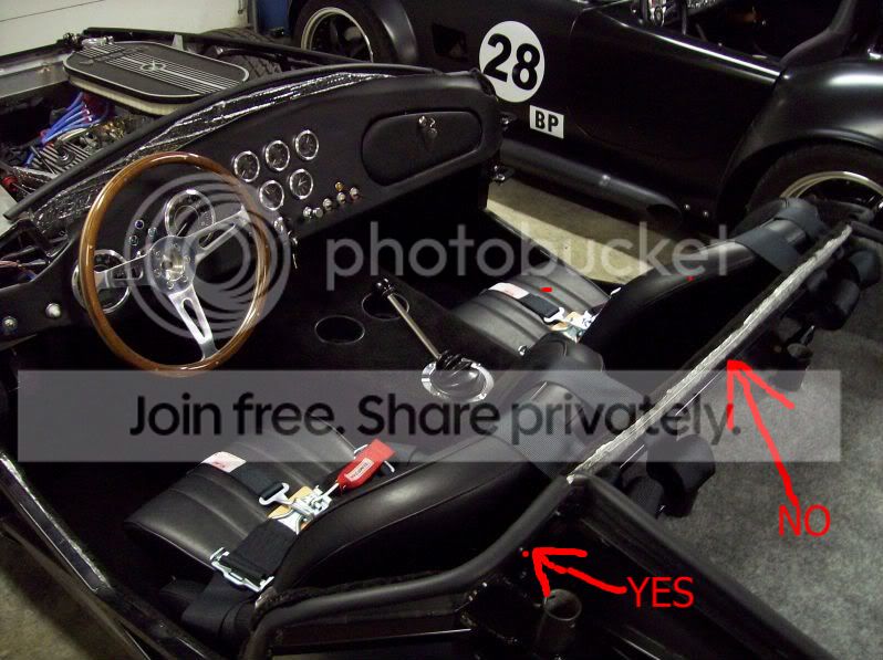
Then, I wanted to confirm that the space for the steering wheel was still good since I made my own Russ Thompson tribute steering shaft locating plate
steering wheel to cowl fitment1.jpg steering wheel to cowl fitment2.jpg steering wheel to cowl fitment3.jpg
Then lastly, I needed to confirm the fitment of the dashpanel to the body cowl. Yes, it fits, but Jeff was right -- I need to trim the corners of my dashpanel down a bit. There was no wiggle room...
checked dashpanel fit to cowl.jpg
Until next time,
Happy Building!
Craig C
-
11-09-2025, 08:06 PM
#388
-
11-09-2025, 08:16 PM
#389
Making another heat shield to stay busy
Hey Y'All,
In my last post of this weekend, I decided to make another heat shield while "noodling" on my dash panel strategy...
It is intended to protect the heater hoses and passenger side wire harness (mainly ECU), but I'm not sure if it is really going to help much. I enjoyed working with my hands on a simple project 
Once again, I used thin polished stainless steel panels...
heater hose and harness heat shield1.jpg
heater hose and harness heat shield2.jpg
heater hose and harness heat shield3.jpg
Until next time, Happy Building!
Craig C
-
11-16-2025, 05:57 PM
#390
I finalized my Dash Panel layout design
Hey Y'All,
I figured out my Dash Panel design
Things I wanted: to cover up the oblong hole for the steering stem, to add some dimension to an otherwise typical "Competition" layout, to have symmetry
Constraints: accommodate how the body cowl edge drops down below the dash hoop tube at the corners, fit the "important" gauges into the space behind the steering wheel so that they fit and can be seen easily while driving, make a trim ring design that would fit the "important" gauges as well as be a reasonable size and shape for a glove box on the other side in a symmetric location
Here's what I decided
gauge layout1.jpg
gauge layout2.jpg
gauge layout3.jpg
and here's the result after careful pilot hole location and use of a drill press with hole saw attached (2 1/8" for the small gauges, 4" for the large ones; this has some accommodation for wrapping with leather or adding powder coating, but is not so large either). Much like the other Builder's, I had some trepidation about cutting up a perfectly good blank dash panel...but I bought a spare, so let's get to cuttin!!
Driver's view
Driver's view of gauge layout.jpg
Overall rear view
overall view of gauge layout.jpg
There's more work to do...but it's finally lookin' like somethin'!
Until next time, Happy Building!
Craig C
-
11-23-2025, 04:53 PM
#391
Making the Dash Panel's trim rings - part 1
Hey Y'All,
In this post, I perform a lot of activity by cutting up 1/4" Al sheet in order to make my Dash Pane's trim rings (but not a lot to show for all the effort )
First up, the roughed out shape. I used a combination of hand tools, a desk-top band saw, and a drill press with various hole saw attachments...
roughed out trim rings.jpg
Then I managed to finalize the perimeter shape for the Driver's side gauge "pod"
gauge trim ring outer perimeter refined.jpg
This week, I plan to refine the inner perimeter shape, then use it as a template for the Glove box trim ring. I plan to do the same for the Console door to copy as a shift boot trim ring
Until next post, Happy Building!
Craig C
-
11-24-2025, 07:53 AM
#392
Not a waxer
-
Post Thanks / Like - 1 Thanks, 0 Likes
-
11-28-2025, 01:02 PM
#393
Thanks for the feedback Jeff...initially they didn't load for me, but after about 30 seconds, they loaded. Not sure if I need to inform the Webmaster?
-
11-30-2025, 05:29 PM
#394
Making the Dash Panel's trim rings - part 2
Hey Y'All,
Hope you had a Happy Thanksgiving!
I spent the better part of last week in the garage working on my Dash panel and console trim rings...
Once I got one trim ring shaped out, I copied it by sandwiching both pieces together and then used a hand-held router with bit to clean up the roughed-out profile.
Here, I copy the Console trim ring for the shifter and handbrake boot trim ring
shift trim ring being copied from console trim ring using hand held router.jpg
and here, I'm in the middle of duplicating the gauge pod trim ring from the glovebox door trim ring
dash trim ring outer edge copied using hand held router.jpg
Next, I proceeded to make the panel doors using flat Al sheet and piano hinges
made glovebox and console doors.jpg
Lastly, here's a picture of my duplicated trim ring for the shifter and handbrake boot (mocked into the planned location)
shifter and handbrake trim ring2.jpg
For those wondering...yes, you can use a big-box-store router bit meant for countertops to cut aluminum...in fact, they performed better than a special spiral-cut bit meant for aluminum (because this special $90 router bit chucked its guide bearings just as I was trying to finish up the shifter & handbrake boot trim ring). Just go slow to feel and hear the metal cutting properly...don't force it...and of course wear safety glasses I saw Ian Roussel do this in one of his TV shows and while initially doubtful, I liked his creativity to use the tools at his disposal...
Next post: more trim ring and panel creation
Craig C
-
11-30-2025, 06:07 PM
#395
Making the Dash Panel's trim rings - part 3
Hey Y'All,
In this last post of the weekend, I thought I'd lead off with a funny image -- Al shavings from the use of router bits on my trim rings ... there's a lot there!
shavings left over from duplicating the gauge pod trim ring.jpg
which was the result of finishing my gauge pod trim ring. I also made a panel "blank" to be cut next...
duplicated gauge pod trim ring and panel blank.jpg
Gauge pod carefully duplicated
gauge pod panel duplicated.jpg
and here, I'm checking the fit to the critical locating factor of the steering shaft collar (so I don't have to make a bezel ring just for it)
checking the fit of the gauge pod panel onto steering shaft.jpg
Lastly, a mockup of my week's long efforts
mockup of dash panel trim rings and panels.jpg
If I designed this right, then I can remove the overall dash panel while the body is mounted
Until next time, Happy Building!
Craig C
-
12-07-2025, 04:36 PM
#396
Fitting the Console trim ring and door
Hey Y'All,
This weekend I fitted my console with the decorative (and reinforcing) trim ring and console door...
Here's a picture with the door closed
fitting console trim ring and door1.jpg
and with the door partially opened
fitting console trim ring and door2.jpg
I still need to locate the latch assembly and bevel the trim ring so that the door opens all the way. The good news is that my plan worked -- the door clears the shifter throughout the travel arc
Next post: finishing the dash panel openings...
Craig C
-
12-07-2025, 04:46 PM
#397
Finishing the dash panel openings
Hey Y'All,
In this last post of the weekend, I trimmed up the new openings in my Dash Panel...and re-checked the overall fit. It's nerve-wracking for me since every hour I put into it will be more effort to duplicate if I mess it up
Here's a picture with the new glove box door closed
more fitting of dash panels1.jpg
and with the door opened
more fitting of dash panels2.jpg
as with the Console trim ring, I'll need to locate/install the latch assembly and bevel (or profile) the trim ring to get the door opening interference-free. I may decide to design an opening limiter anyway...
Also, I decided to design my glove box as a shallow assembly of laminated pieces fastened by the trim ring bolts
Until next time, Happy Building!
Craig C
-
12-14-2025, 05:30 PM
#398
Profiling the Console trim ring bezel and creating the glovebox
Hey Y'All,
This past week I spent detailing out the Console and Shift Boot trim ring bezels. I used quarter round router bits and hand files. I still need to polish them...but that can wait for later.
Here's a picture:
profiled console and shift bezel trim rings.jpg
Then, I designed my glovebox. It couldn't be very deep and I wanted to continue to get practice using the hand-held router, so I made it out of ABS plastic and layered several sheets together to get the depth. Here's a work-in-progress using hole saws...
cutting out the glovebox laminate.jpg
Here's some details:
glovebox detail1.jpg glovebox detail2.jpg
and mocked into position
glovebox mockup.jpg
Next post: profiling the dash panel's trim ring bezels...
Craig C
-
12-14-2025, 06:11 PM
#399
-
12-14-2025, 06:58 PM
#400
Not a waxer
Photos still aren’t loading Craig. Don’t know why—-everyone else’s are working for me
Jeff


 Thanks:
  Likes:


 Reply With Quote

