-
-
Post Thanks / Like - 0 Thanks, 1 Likes
-
Radiator and condenser install
I now have the radiator and condenser installed in the car. I ended up taking Breeze Shroud and fan off and rotating it 180 degrees so that the angle part of the shroud is at the bottom. I did this because I wanted to push the radiator as vertical as I could get it because the hood hinge hits the lower AC attachment. I became aware of the hinge issue watching the Oak Hollow YouTube channel and then read PaulB's thread and saw he described the same issue. So this was my first experience drilling out rivets, which went well. I put 10-32 button heads, washers, and lock nuts in the enlarged holes which will allow me too take the shroud off if I need to. Shoutout to Yellville and his YouTube channel for his video on AC installation - it help me to see his setup.
Here is a photo of the passenger side hood hinge hitting the AC fitting:
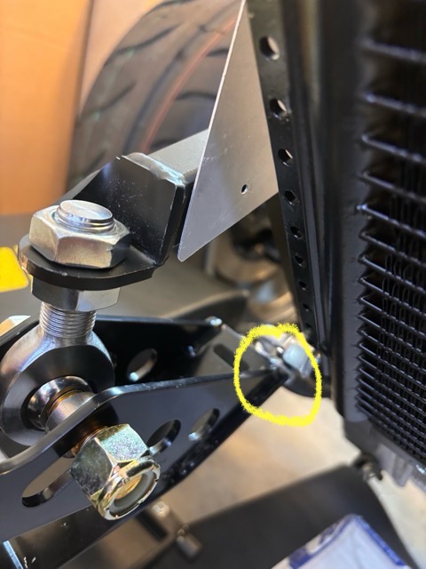
I figure I will have to cut the end of the hinge off and make a new elongated hole.
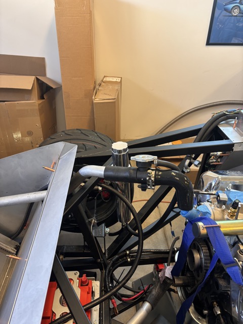
Also installed the expansion tank. Used some L shape aluminum to create a bracket to mount the lower support - after I did this I came across a flat piece of metal in the box that was meant for this purpose! Well I had fun with my L shaped bracket and installing rivnuts into it.
I glued inner tube rubber to the underside of the radiator mount rather than using the half moon weather stripping described in the manual. And I used contact adhesive and zip ties to connect the split fuel tube to the bottom radiator mounts.
This photo shows the expansion tank and the 90 degree hose that will hopefully connect to a new thermostat housing that has a vertical connection that I'm waiting for delivery on.
I also just received some 5/8 Pex hose clamps which I used on the vent tube coming out of the bottom of the tank; seems to work well - my mechanic buddy prefers these to the standard hose clamps.
Next is installing the drier, and making AC hoses. Unless I get distracted by setting up the carb linkage which is quite the puzzle.
-
Looks great John! I have the same tight fit of my radiator. Agree that the lower radiator connection is VERY tight. Question on the Forte mechanical throttle linkage -- is there any play in the pedal where it goes through the aluminum into the engine compartment....mine definitely has a little bit of play to it and I saw Scott's at the FFR event last year and his has a bit of play when installed as well. Wondering if this is how they are supposed to be or if it is maybe just a few that are that way.
Also where your hinge strikes the AC evaporator fitting - once you have the struts fitted for the hood, theoretically that will be the "stop" that prevents the hinge from rotating that far where it strikes the AC fitting....I guess we will find out!
-
-
I thought I wanted a darker blue for my type 65 but man, that is one gorgeous color on your beast!  having second thoughts!
Can you get me info on where to get those beautiful wheels?
Thanks
-

Originally Posted by
TechT

I thought I wanted a darker blue for my type 65 but man, that is one gorgeous color on your beast!
having second thoughts!
Can you get me info on where to get those beautiful wheels?
Thanks
Hi TechT,
If your talking about the pictures I posted back in post #8 that is not may car, but it is the color and scheme that I want. It is one of the Gen 3 Type 65s that Factory Five built; I saw it in their showroom at the factory back in 2022. If you look at the Type 65 page on their website you will see it. I think the wheels at 19s but I don't know what brand - I expect that they can give you the info.
-

Originally Posted by
jgray
Hi Hank,
I appear to have been able to get rid of the slop in the Forte throttle pedal by adding two washers and tapping into the male part of the throttle pedal splined connector and screwing in a bolt. I did this back in January, and tried to describe it with photos, but now I see the photos are missing and my description is drawn out across several posts. So let me try again!
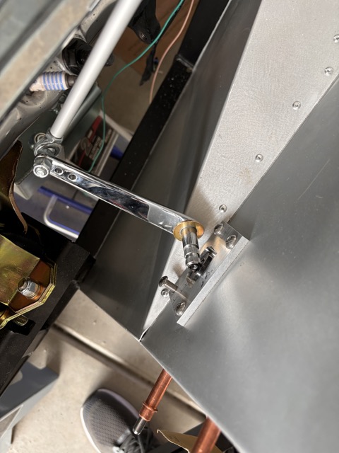
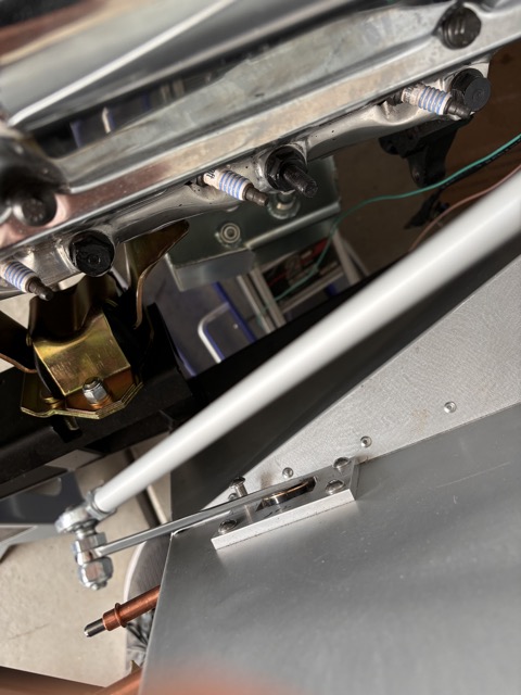
Here are some photos from today. I recently took the throttle pedal assembly apart to angle the part in the engine bay towards the front of the car, pointing at a 10 oclock rather than straight up. I did this to get the throttle linkage arm on the firewall further away from the firewall. The result is the pedal can go through its full range of motion without the arm hitting the firewall. I could have shortened the linkage but then the linkage would be at a more vertical angle which would reduce the rotation of the arm on the firewall. I fully expect to be rejiggering this whole setup again to get the correct of movement at the far end of the throttle linkage where it connects to carb linkage. And then there is the consideration of whether the movement of that end is linear with the movement of the pedal. Lots of places to make adjustments once everything is connected.
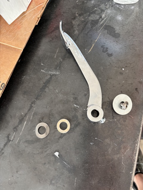
This shot shows the 1/4 -20 bolt and large washer. The bolt goes into the threaded blind hole in the male throttle pedal spline. The washer helps pull the male spline into the female spline. Once it is tight I then tightened the set screw that goes through the female spline. The other washers are a slim washer which came with my Wilwoods, and the spring washer which came with the throttle linkage. Overall my aim was to eliminate the side to side slop, which I appear to have done. I say appear because I wont know for sure until everything is hooked up.
This shot shows the end of the throttle in the engine bay showing the washer that I added on this side and if you zoom in you can see the blind hole that is threaded
Another shot of the engine bay side. The washer is a another thin washer that was an extra from my Wilwoods:
And here is a shot from the footbox and you can see the bolt and the washer. I am swapping the four bolts on the bracket so that the bolt heads are in the footbox and lock nut in the engine bay.
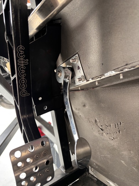
An issue that I have is I cannot put my foot on the gas pedal without hitting the brake, even withe brake pedal pad moved over to the leftmost position. I am figuring I will need special skinny shoes, and not my regular shoes!
I ended up making a custom panel for that one and gained several inches of space.
20230316_155837.jpg20230414_134313.jpg
-
Thanks for the input! Nice solution! I was looking at the panel this morning wondering how hard it would be to drill out the rivets and make a replacement panel. You have me given me cause to take another look. I have test fitted the engine and will be pulling it back out soon; so now is the time. Thanks
-
Originally Posted by
jgray
Thanks for the input! Nice solution! I was looking at the panel this morning wondering how hard it would be to drill out the rivets and make a replacement panel. You have me given me cause to take another look. I have test fitted the engine and will be pulling it back out soon; so now is the time. Thanks
1/8 inch drill bit will make short work of it.
-
After taking 3 months off, partly due to how hot it was this summer/fall and part sheer laziness, I am back working on the Type 65. Earlier this week we dropped the engine and transmission in. It only took about 90 minutes, which included modifying the transmission mount (special thanks to Shakey for all the photos and explanatory notes). Everything went fairly smoothly. We ended up using a piece of wood and a mini sledgehammer to whack the driver-side engine mount so that it would move the last 1/4 of an inch!
Since then i've installed the starter, engine ground, run wires to the solenoid and a few other little things. At this point I am quite excited to get moving on the list of 35 items I need to get done for first start! I feel like I have overcome a big hurdle; for me, since I have never done any of this type of work before, each step is an accomplishment.
-
Post Thanks / Like - 0 Thanks, 3 Likes
-
Epic experience - First Start
So I am 60 years old now. When I was 18, I had pictures of kit cars on my wall. My dream was to build one and hear the engine start. So, 42 years later, it happened. And with the four dual IDF 48s, the sound was epic!
The pictures show the car on my driveway, ready for my buddies to come over and help. Fortunately, the fire extinguisher was not needed!


I set the timing at 10 degrees. The fuel regulator was set at 5 psi, which is a bit more than what is recommended for webers. I have an electric pump in the tank and a return system, so there is plenty of fuel supplied to the carbs. I had tested the fuel system ahead of startup by putting an AN6 nut on the end of the first hose that goes to the carbs, and there were no leaks. Once I put the carbs on I could see fuel coming out of the accelerator jets. Initially, one of the carbs was dripping and my buddy advised me to tap on top of the carb because it was likely the float was stuck. Sure enough, he was right, the dripping stopped.
I tested the MSD electronic ignition by shorting the wire from the distributor and I got a spark from the coil wire. I had also turned the key to bump the starter to make sure it was getting power. I pressure tested the coolant system and it held pressure. Lastly, I ran a drill with an extension to turn the oil pump until oil spilled out of the rockers. So I figured I had tested as many systems as I could individually. I was tempted to try to fire it up on my own, but realized that I was not really sure what to do if it fired. I knew the engine had roller cams and that made the initial run up simpler. But I patiently waited for my more experience buddies to turn up.
After 30 minutes of chatting and checking a few things we decided to fire it up. First we turned it over a few times with the coil disconnected to move oil around. I was happy just to hear the engine cranking. We pumped the throttle 3 times. Then we connected the coil wires and I turned the key. It started almost immediately! And what a sound!! We ran it for 20 seconds and then my master mechanic buddy yelled at me to shut it down. I thought something was wrong, but this is his standard procedure to check for leaks. We found oil dripping on the driver's side. I traced it to oil pressure sender which I had not fully tightened.
We then fired it up again and ran it for a minute or so before it started to cut out. I realized the fuel pump wasn't working. I had forgotten to re-attach the connector on the tank! I put that back on and we then ran it for about 10 minutes. Oil pressure was between 55 and 75. The coolant temperature came up slowly and at 185 the fan turned on. Volts we are just over 14, so the alternator was working.
On further inspection we found some coolant dripping into the passenger footwell. I found that I hadn't fully tightened the hoses that go to the back of the evaporator.
At this point we fired it back up and starting using a heat gun to see the temperature of the headers to make sure each cylinder was firing - which it was. However, one of the carbs does not idle well, so I need to take that carb off to see if the idle circuit or idle jet is blocked - that is about it.
I talked to Mike Forte this morning and my custom driveshaft is on its way and should be delivered next Monday. So go-carting may occur next week. The driveshaft has a been a challenge due to the 302 + T56 combo. Mike sent me a different (shorter) pinion flange to install and measure. With this flange installed the driveshaft is 10 5/16 from pinion flange to transmission seal, so still very short.
I am currently working on getting the alignment "in the ball park" so that I can go-cart. The ride height is 4.5 inches which I read is standard, and that is without the body on which I figure may weigh it down some.
Here is a picture of my transmission mount, which I cut and welded angle iron onto. This was necessary due to the 302 + T56 combo. A big shoutout to Shakey for leading the way on this modification. I followed his approach and it worked out great! I too have a cheap flux core welder and mediocre welding skills!

Hopefully I will be posting soon describing my first drive!
-
Post Thanks / Like - 0 Thanks, 4 Likes
-
Way to go! That sounds very exciting
-
Post Thanks / Like - 1 Thanks, 0 Likes
 jgray
jgray thanked for this post
-
Congratulations John! It's an epic experience and I cannot wait to see it on the road soon.
-
Post Thanks / Like - 1 Thanks, 0 Likes
jgray thanked for this post
-
That is awesome! Glad to see your dream come to life.
-
Post Thanks / Like - 1 Thanks, 0 Likes
jgray thanked for this post
-
Congrats John, awesome looking engine and build! Keep up the good work! Excited to see your first drive experience.
-
Making some decent progress; about to start installing the body. Here is a new YouTube (hard to believe its 16 months since I created the last one): https://youtu.be/js5l4YNP4x8
-
Post Thanks / Like - 0 Thanks, 1 Likes
-
Body work begins
Last week I got some help and we got the body on. Since then I got one door on, which took 2 days! Yesterday I put both side pipes on and went for a little drive! What fun!! The hood is in but by no means completely installed. I will install the other door and then tackle the hood. I know to install the hood supports as they push the hood forward.


-
Post Thanks / Like - 0 Thanks, 1 Likes
-
Time Flies - Door difficulties
Almost a year since I posted! The car is driveable but is by no means done!! Probably never will be.
The purpose of this post relates to the picture down below, with the question: Is this normal, and if not, what am I doing wrong?
Preamble and catchup:
What is funny/ironic, is looking in my garage today: the car, tools, stool, vacuum are all pretty much in the same positions! Between last May and today I have put over 1000 miles on the car and had a ton of fun. However, I did a crap job installing the p/s door. I was so eager to drive the car, I got door basically hung called it good!
Now, I am down with a failed power steering pump, the AC has stopped leaking, my carbs are overheating (fuel soak), and I have an oil leak! Since I am doing all of this I decided to unhack some of my hacks!
Mike Forte sent me a new PS pump free of charge, despite the old one being almost 2 years old. Thank you Mike! I have it installed and it looks good. I have remade an AC line that I thought was the problem and have bought a sniffer to find leaks. For the carbs I have some quarter inch phenolic resin gaskets that should help. I took the opportunity, and sucked up the courage, to take all the carbs (four dual downdraft IDF 44s) apart and cleaned them in my ultrasonic cleaner. Suprisingly (to me) I as able to get them back together with no left over parts. I replaced the oil pan (Canton) gasket in the fall because I had a leak; I had a lot of difficultly getting it on (crawling under the car) and ended still having a smaller leak. I am going to go over to a friends who has a lift and redo it.
However, what I am working on currently is fitting the passenger side door. I took too much material off the front of the door and too much around the hinges so I will be added some material back - I already did a test of adding fiberglass matting with resin to an offcut (the door cutout) and am extremely impressed by how strong it is - I only ground down the gelcoat on about half an inch an was able to get an extremely strong bond using vinylester resin.
All of this brings me to the reason for this post, which is the fitment, or lack thereof, of the lower rear part of the door. I have been jiggering the door for few hours and am happy with the fitment other than this one spot, as shown in the photo. Is this normal, and if not, what am I doing wrong? If it is normal I can add fiberglass and filler to make everything align but it feels like a bit of a hack.

I will be painting the car myself, partly because I want to, and partly to save money.
Over winter, when my wife was out of town, I built a small room in my garage to house my compressor plus an add on to house two extractor fans so that I can turn the front two stalls of my two wide two deep garage into a paint booth. The fans pull 4000 CFM, so I should have good air flow. The reason I did this while my wife was gone was because it involved cutting three holes through the garage wall (the compressor closet has a small extractor fan - 400 CFM) plus I had never done anything like this. It came out well and she did not even notice initially!


-
Post Thanks / Like - 0 Thanks, 1 Likes
-
You might be able to pull that part of the door in twords the body better by adding a spacer (washer(s)) between the inner door skin and the metal door frame. I believe EdwardB had to do it and so did I. It worked well.
Scott
-
Thanks Scott! Late last night I figured that out. I guess I should have re-read your and Edward's threads. So the door fits pretty well now. I have to add some fiberglass back but that is not too big a deal. Now I am on to working on the windows - I was just looking at your build album and you have some great pictures!
-
Originally Posted by
jgray
Thanks Scott! Late last night I figured that out. I guess I should have re-read your and Edward's threads. So the door fits pretty well now. I have to add some fiberglass back but that is not too big a deal. Now I am on to working on the windows - I was just looking at your build album and you have some great pictures!
Thank you Sir!! I believe my picture album is also public. Might be easier to find a pic there then going thru the build page by page. It's a really good feeling when your build thread is mentioned in the same sentance as Paul's (EdwardB's)!
Scott
-
Post Thanks / Like - 0 Thanks, 1 Likes


 Thanks:
  Likes:


 Reply With Quote
