-
02-23-2024, 09:07 AM
#201
Hood fitting
While fitting the hood, I discovered three surprises.
The build manual is really lacking in the hood area. Some examples... I couldn't find anywhere in the manual about installing the bracket to the hood (where the hinge arm attaches); one picture shows a different bracket (i.e., the hood bracket is point down vs forward in one of the pictures).
However, after determining the bracket points forward and making a decision on the position of the backet (again, the manual has noting on this step) I marked where to drill the mounting holes. I had assumed I would need to install rivet nuts to install the 1/4-20 button head bolts. Luckly, I drilled the pilot hole first with a 13/64" bit only to discover that the fiberglass mounting area is backed by aluminum. So, I could tap the threads needed vs using rivet nuts. Again, the manual makes no reference to this. Had I drilled the 3/8" hole needed for the rivet nuts, I'd been screwed! Ref pic 1 below, after I drilled the pilot holes, I simply followed up with a drill/tap bit for the 1/4-20 threads needed for the button head bolts

When I was fitting the hood to the cowl, it was raised up on the driver's side. Looking under the hood, I saw the bottom of the hood raised area was hitting the Tilton 3 lids of the brake fluid container. So, I applied painters' tape to the hood area hitting the lids, took a marker to trace around the 3 lids so I knew where to cut the reliefs. The next pic shows I used a hole saw without the pilot bit.

The next shot shows the hood back on and the brake fluid lids fitting nicely in the 3 reliefs I cut.

When I do the body work on the hood, I'll fill the three cavities to finish this area.
Stay Tuned,
Mark
-
02-24-2024, 08:22 AM
#202
As a follow up to the above Hood post above....
While installing the latch post/pin to the hood, I discovered Aluminum there also, so drill carefully so you can tap with a 1/4-20 thread. The manual says install rivet nuts so it's wrong again.
While installing the hood prop rod bracket, that is hollow fiberglass (no aluminum) and I installed 10-32 rivet nuts for that application. The prop rod also needs shorten... I cut off about 2.5".

Installing the actual latch to the firewall is a bit tedious to ensure the latch post/pin and the latch is aligned and set to the proper vertical depth. I just applied tape to the firewall, hood closed and flashlight in hand I could use a marker to locate the pin on the firewall.

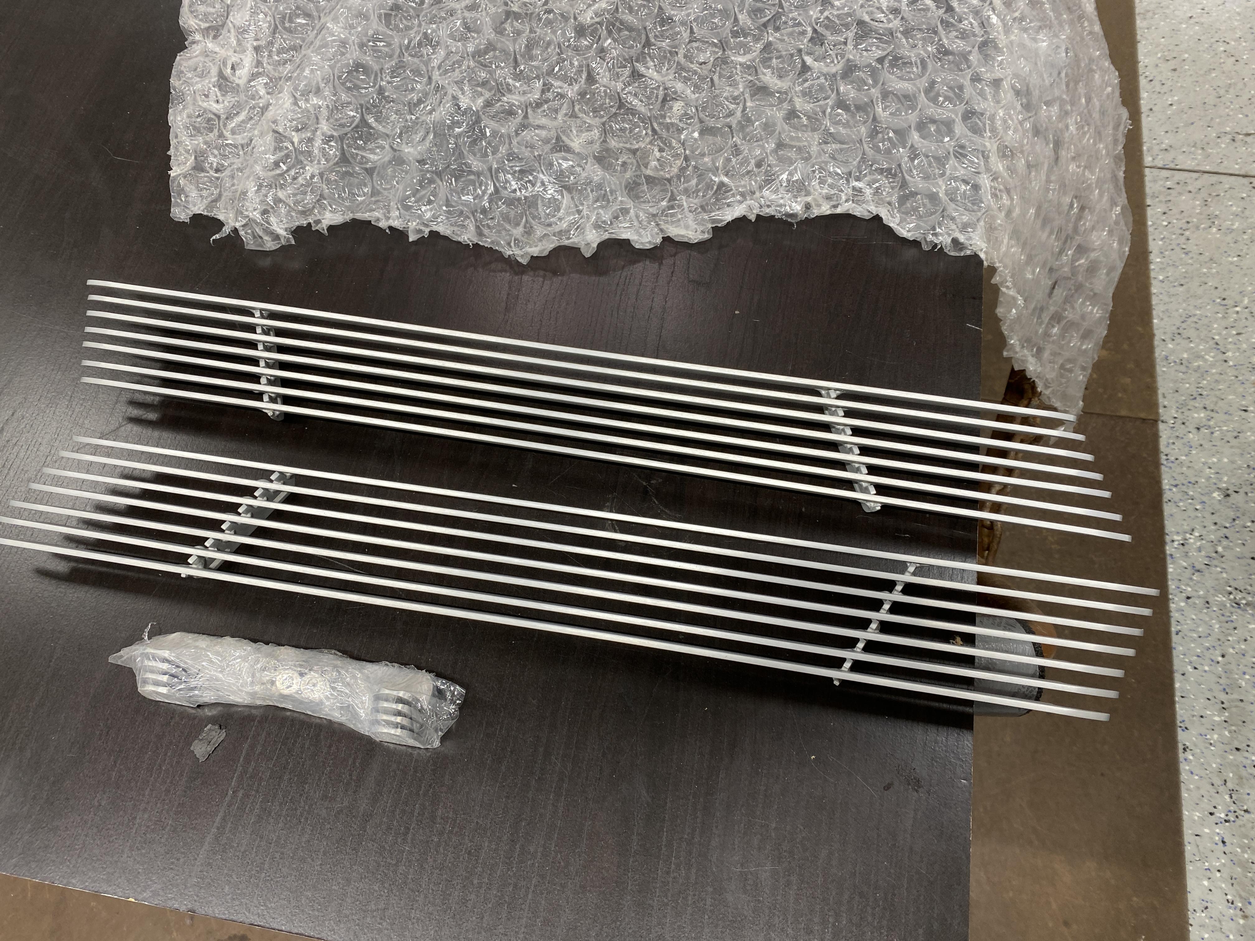
Update on the grill shroud. FFR is sending me a new one as the original was not trimmed correctly at the factory (i.e., the right side was trimmed to much to make it all fit properly). Once the new shroud is fitted, I can move on to the engine bay side covers.
Today, I'll focus on fabricating the brackets to hold the ECU and radiator overflow tank. Both will be installed in the area between the back of the radiator fan and the front of the engine. I'll document all that later.
Mark
Last edited by mkassab; 02-24-2024 at 12:47 PM.
-
02-26-2024, 01:17 PM
#203
-
02-27-2024, 07:49 AM
#204
-
02-28-2024, 08:16 AM
#205
Emergency Hood Latch Release
Yesyerday, I ended my update post with a little tease, i.e., having a backup to open my hood in case the latch cable broke.
I first removed the latch from the firewall to help me figure out what options I had. Once removed, I noticed a small hole in the latch arm next to the post that holds the cable for the factory pull latch opener. Once I saw that hole, I then knew exactly what I would do. You see, back in the day with carburetors, we used a simple manual choke pull cable. Well, as it happens, I had one laying around from a previous car build I never used.... the package was a bit dusty... but it will work

Since the Holley choke cable was very long and would need cut, I first mounted the pull knob in an area I could get to open the hood if ever needed. I chose the left side lower firewall. I mounted the L bracket (a left-over parts from the FFR emergency brake handle kit I didn't use) to one of the bolts that held my gas pedal in place

Then routed the cable end up to the hood latch. Once I determined the length needed, I carefully cut the cable housing with a Dremel cutting disc.

Once the cable housing was removed and I then cut the actual cable/wire, I bent the wire in the Z shape that will be installed into the latch hole

This last pic shows the wire/cable installed and ready to remount to the firewall. I did some test and it opened/closed just fine.

Later,
Mark
-
02-28-2024, 03:01 PM
#206
Does the latch have enough strength to reset itself with that attached?
Mike
-
02-28-2024, 03:59 PM
#207

Originally Posted by
michael everson

Does the latch have enough strength to reset itself with that attached?
Mike
Hi Mike... the latch works just fine.... i.e., no difference at all before or after I installed the backup pull latch opener.
Thx the the question
Mark
-
02-29-2024, 07:41 AM
#208
Misc Electrical, E-Stopp and Horn
While waiting for my new radiator/grill cowl, I'm doing other odds and ends, e.g.., more electrical connections, audio wirings, etc.
I finished connecting my E-Stopp electric emergency brake. The instructions said to connect the blue wire to the Ignition Switch so the brake can't be switch on while driving (i.e., If the blue wire senses +12v, you can't set or un-set the e-brake) . I didn't like that because it would mean I'd have to turn off the ignition system before I could set the emergency/parking brake. So, what I did was use the brake light wire and a relay. As most of you know, the relay has a Normally Closed (NC) and a Normally Open (NO) circuit. I connected the Blue wire to the NC which provides the +12v, thereby, preventing the e-Brake from being set. The +12v needed to trigger the relay to change from NC to NO comes from the Brake Light circuit. Thereby, when I depress the brake pedal and the brake light circuit is energized, the relay sends +12v to the NO (open/not connected to anything) and removing the +12v from the NC. With the +12v now removed from the Blue wire, I can set the e-brake. I also will have to press the brake pedal to release the e-brake. I think this is much better then the ignition switch.
I also mounted my Ah-ooo-gah horn. I took advantage of one of the mounting bolts from the coolant overflow can. I used a U shape bracket and a hose clamp around the horn's motor and over the U shape bracket. It's a very secure mount.


more to come,
Mark
-
02-29-2024, 01:07 PM
#209
I had a PM asking about my Exhaust H set up and why I did it. I'll answer in here in my build thread so all can read the response.
An H or X-Pipe is better for the exhaust vs straight pipes.
Why an X-Pipe?
An X-Pipe is, you guessed it, shaped like an x, and allows the exhaust to flow down the path of least resistance. At lower revs, turbulence is formed as exhaust gases try to shuffle past a second column of gases coming from the other side. While always producing more power than the restrictive factory system, the potential gains are not seen until higher rpms are reached. This is where an X-Pipe stands apart from the rest. Exhaust gas is pushed out harder as the engine spins faster. The X-Pipe merges this chaos into two uniform streams, allowing a smooth flow from engine to tailpipe.
Both streams keep each other up to speed, which draws even more spent exhaust out the cylinders. Magnaflow X-Pipes provide a boost in horsepower and a higher tone akin to an exotic car.
Why an H-Pipe?
An H-Pipe is also shaped like its namesake and relies on exhaust expansion to balance the cylinder banks. A small section of tubing in between the main pipes provides an area for gases to expand into during exhaust pulses. Only a small amount of exhaust flows from one stream to the other as both sides push back and forth in the center section. Flow master H-Pipes feature low restriction, so gains in performance are noticed from low rpm and give the exhaust a deeper, muscle car-like tone.
While both X and H pipes serve the same purpose, they use different methods to build power and economy, all while providing a distinctive sound. Think of an X-Pipe as being at home in a high-winding modern V6 or V8 while an H-Pipe conjures memories of tire-shredding torque in classic American iron.
An X-pipe's supposed advantage is that because the bends are smoother at the convergence, the flow and scavenging are both better, and hence the X-pipe is worth more power.
Most V8s do not fire symmetrically, i.e. alternating left bank right bank, so the X or H pipe balances the pulses or waves between the two mufflers and tailpipes creating a more efficient flow..
Hopes this helps.
Mark
-
02-29-2024, 03:28 PM
#210
-
02-29-2024, 04:18 PM
#211
Originally Posted by
Just 1 More
Thanks Just 1 More.... this Engine Masters video resulted it what I've heard...... H pipe better for lower RPM and thumper sound. The X pipe sound (based on a previous build I've done) sound more high rev/sports car sound.
For my truck, I like the thumper sound. At the end of the day.... each his/her own there is no wrong answer.
Thanks for sharing.
Mark
-
03-01-2024, 10:33 AM
#212
-
03-02-2024, 10:18 AM
#213
Headlight and Taillight mockups
Some lessons learned and modifications of the Headlight and Taillight wiring instructions and my mockups.
First the Headlights. The instructions refer to the smaller red and green wires on the back of the headlight unit. Well, they are red and yellow. They also refer to the red as DRL (daylight running lights) and the yellow (green) as the turn signal. If you want DRLs you need to run a +12v hot from the ignition sw. Our wire harness has to each headlight a ground, Hi beam, Low beam, turn and Park). I didn't want DRL, so I connected the Red to the Park and the Yellow to the Turn. The park is a White light, and the turn is Amber light. As you'll see in the pic, I ran the two extra wires in the plastic sleeve.

For the taillights, the first pic is showing the spliced wires that will run through the flexible coil SS wire conduit

As you'll see in the next pic, I didn't follow the instructions by drilling a 1/8" hole in the bulb socket plate. Instead, I removed the entire socket that's pressed in the taillight housing.

After cutting the 12" length of the flexible coil SS wire conduit, I ran the wires through the cut end first and then put the cut end into the taillight housing and used a hot glue gun to hold the coil and wires in place. The next two pics show both taillights. What you don't see in the pictures is I also hot glued the outside also. The provided wire way cover will cover the hot glue.


On a side note, the 2K clear coat came out so well, I'm also going to clear coat the engine bay side cover vents and the brushed aluminum windshield wipers.
more to follow,
Mark
-
03-07-2024, 08:32 AM
#214
-
03-09-2024, 09:19 AM
#215
Evans waterless coolant/antifreeze added with Airlift
With the coolant system all buttoned up, it's time to add the coolant.
I'm using a waterless coolant product by Evans. With no water, the boiling point is very high at ~375* F and no corrosion. Also, with the high boiling point, the PSI is very low at ~4-5psi. Lastly, it's more efficient of cooling the engine with the heat transfer being better than water. I've used this product before with very good results.
For adding the coolant, I'm using my Airlift system I've used in every build and personal auto.
The Airlift provides several benefits:
1. It works by first drawing a vacuum on the cooling system. Once the vacuum gets to ~26 you close the valve. This will hold the vacuum if you have no leaks anywhere. If the vacuum starts to drop, you find the leak and fix it.
2. Once the system holds the vacuum, you place the Evans antifreeze in a bucket, drop in a pickup hose and attach the other end of the pickup hose to the valve. When you open the valve, the vacuum will suck in the antifreeze with no voids and eliminating any hot spots.
The lid of the Airlift and instructions

Filling the 5 gal bucket with antifreeze. The coolant is the color of apple juice.

In the next pic, you see the air compressor airline connected to the valve. When air passes through the Venturi Assembly, it creates a vacuum in the cooling system via the venturi effect. Note the Vacuum gauge showing ~26. A reading of 30 is considered a full 100% vacuum.... but the system used here will only go to ~26. With a vacuum pump used on the AC system you can get to ~29.

In the last pic below, you can see the vacuum on the cooling system sucking up the antifreeze out of the bucket, thereby filling the radiator, engine block, heater and all the hoses.

Mark
-
03-11-2024, 08:41 AM
#216
Early '30s Ford Radiator cap/Thermometer
A friend of mind gave me a well made replica of a Ford's early "30s radiator cap thermometer. It's really well made and functional.
I'm thinking of mounting it on my grill/radiator cowl. I'd like any feedback on this as our "35 builds would have had one.

And the back side clearly showing the thermometer.

Your thoughts most welcome.
The base of the thermometer is brass and has 7/16-20 threads.
Thx Mark
-
03-15-2024, 01:06 PM
#217
Hood to grill cowl fitment issues... need advice/help.
I'm now fitting the hood to the grill cowl. My issue and what I need help/advice with is the front left and right bottom of the hood. The issue is the hood is tight against the cowl. I know the lower part of the hood gets trimmed to fit the engine bay side covers, but the hood is still too narrow and tight against the cowl. The cowl is pulled tight against frame's mounting tab.... so, it's the hood vs the cowl.
I'd think I'm not the only one with this issue and I'm looking for guidance/help on what to do. Any ideas weldcome.
Left side looking forward.... you can see cowl sticking out.

Right side with cowl sticking out.

Help,
Mark
-
03-15-2024, 02:21 PM
#218
Mark, I have exactly the same issue. I thought with the bottom edge trimmed, that that would be sufficient, but I'm having my doubts. Can't pull the cowl in any tighter. Does the entire rear edge of the cowl need to be trimmed off ? DonS
-
03-15-2024, 02:54 PM
#219
Mine was the same way. Also didn't sit flat, e.g. was high on one side versus the other. Don't remember who suggested it, but I put bumpers all around the cowl that forced it out to match. Then put the hood out in direct sunlight on my driveway for a couple hours. In the summer for Michigan. Not now. ") The black absorbs heat so it got pretty warm. Quickly moved it back onto the chassis and the bumpers and strapped down. Left if for a day or whatever and it matched quite well and sat flat. Your experience may vary but that worked for me.
The black absorbs heat so it got pretty warm. Quickly moved it back onto the chassis and the bumpers and strapped down. Left if for a day or whatever and it matched quite well and sat flat. Your experience may vary but that worked for me.
I had a similar issue in the front where the hood matches the radiator surround and engine covers. It pinched there a bit too. I wasn't as successful getting it a lot better. I sanded the underside of the hood in that area as much as I thought I could and also ended up putting Xpel on the engine sides to keep from damaging the paint as it opened and closed. It was pretty OK but never perfect.
In general, I spent a lot of time getting all the fiberglass pieces to match up acceptably. Once painted, it all blended together and looked decent. But not sure it's possible to get the same fit and gaps as a metal body. Not without way more time and effort than I was willing to spend.
Build 1: Mk3 Roadster #5125. Sold 11/08/2014.
Build 2: Mk4 Roadster #7750. Sold 04/10/2017.
Build 3: Mk4 Roadster 20th Anniversary #8674. Sold 09/07/2020.
Build Thread and
Video.
Build 4: Gen 3 Type 65 Coupe #59. Gen 3 Coyote. Legal 03/04/2020.
Build Thread.
Build 5: 35 Hot Rod Truck #138.
Build Thread. Sold 11/9/2023.
Build 6: Mk5 Roadster 30th Anniversary #11,258.
Build Thread.
-
03-15-2024, 05:59 PM
#220
Originally Posted by
DonS
Mark, I have exactly the same issue. I thought with the bottom edge trimmed, that that would be sufficient, but I'm having my doubts. Can't pull the cowl in any tighter. Does the entire rear edge of the cowl need to be trimmed off ? DonS
Don, I don't think you wand to remove the rear edge of the cowl.... there must be another way.
Mark
-
03-15-2024, 06:14 PM
#221
Originally Posted by
edwardb
Mine was the same way. Also didn't sit flat, e.g. was high on one side versus the other. Don't remember who suggested it, but I put bumpers all around the cowl that forced it out to match. Then put the hood out in direct sunlight on my driveway for a couple hours. In the summer for Michigan. Not now.
The black absorbs heat so it got pretty warm. Quickly moved it back onto the chassis and the bumpers and strapped down. Left if for a day or whatever and it matched quite well and sat flat. Your experience may vary but that worked for me.
I had a similar issue in the front where the hood matches the radiator surround and engine covers. It pinched there a bit too. I wasn't as successful getting it a lot better. I sanded the underside of the hood in that area as much as I thought I could and also ended up putting Xpel on the engine sides to keep from damaging the paint as it opened and closed. It was pretty OK but never perfect.
In general, I spent a lot of time getting all the fiberglass pieces to match up acceptably. Once painted, it all blended together and looked decent. But not sure it's possible to get the same fit and gaps as a metal body. Not without way more time and effort than I was willing to spend.
Thanks Paul. I'll try the sun.
When you put the rubber bumpers on the cowl.... how did you prevent the open hood from smashing the bumpers when closing it?
I have a couple ideas:
1. I was thinking of a wedge type deal made of steel or aluminum where the hood would hit the very thin part of the wedge and being forced open/out as the hood is closed.
2. I was also going to experiment with a thick wedge between the bracket on the underside of the hood where the hinge bracket connects to see if the hood bottom side would spread some.... but the bracket may be too far back from the front of the hood to help any in that area?
3. Lastly, another thought that occurred to me was some sort of rod from the underside of the center of the hood, one left and one right... i.e., rod from center of the hood to the lower inside corner of the front of the hood to "push" it out? I realize there's lot of obstacles to get around, e.g., top coolant hose/cap, etc. If the obstacles can be overcome, the center of the underside of the hood would need stiffen/built up so the rod force does cause an hump/bump in the top of the hood.
Anyway.... I'll wait to see if others chime in
Thanks
-
03-15-2024, 08:06 PM
#222
Originally Posted by
mkassab
Thanks Paul. I'll try the sun.
When you put the rubber bumpers on the cowl.... how did you prevent the open hood from smashing the bumpers when closing it?
Don't overcomplicate it. Try simple first. I found once it was in the sun and relaxed against the bumpers, it opened and closed without the bumpers being a factor. I also used medium hard ones.
Build 1: Mk3 Roadster #5125. Sold 11/08/2014.
Build 2: Mk4 Roadster #7750. Sold 04/10/2017.
Build 3: Mk4 Roadster 20th Anniversary #8674. Sold 09/07/2020.
Build Thread and
Video.
Build 4: Gen 3 Type 65 Coupe #59. Gen 3 Coyote. Legal 03/04/2020.
Build Thread.
Build 5: 35 Hot Rod Truck #138.
Build Thread. Sold 11/9/2023.
Build 6: Mk5 Roadster 30th Anniversary #11,258.
Build Thread.
-
03-16-2024, 11:58 AM
#223
Front hood widening.
OK, based on some input from Paul.... my first attempt to "bow" out the lower corners of the front of the hood is shown in the pics below. I pulled each corner out about 3/8" and wedged some wood blocks between the fiberglass and the hinge arms. I then applied heat via a heat gun both outside and inside the hood area. I'll do this several times a day over several days and let the blocks in for several days.
Lastly, the button head screws that hold the engine side covers via a bracket that bolts to the grill cowl will also hold the hood out. The button head can be adjusted out by adding washers as needed. I'll also bevel the inside of the hood to help the hood slide over the button head.


Fingers Crossed,
Mark
-
03-16-2024, 12:42 PM
#224
Originally Posted by
mkassab
OK, based on some input from Paul.... my first attempt to "bow" out the lower corners of the front of the hood is shown in the pics below. I pulled each corner out about 3/8" and wedged some wood blocks between the fiberglass and the hinge arms. I then applied heat via a heat gun both outside and inside the hood area. I'll do this several times a day over several days and let the blocks in for several days.
Lastly, the button head screws that hold the engine side covers via a bracket that bolts to the grill cowl will also hold the hood out. The button head can be adjusted out by adding washers as needed. I'll also bevel the inside of the hood to help the hood slide over the button head.
Fingers Crossed,
Mark
Hey Mark, I found that the button heads spread the front of the hood out to very close to even. At the rear I’m considering a positioning wedge for lining up as it closes.
For the doors I found that your knee at bottom and pulling out the top as you tighten the bolts gives a lot of adjustment. Also I read on facebook where someone used a couple of pipe wrenches to twist the door metal for top to bottom alignment.
Lewis
-
03-16-2024, 01:46 PM
#225
Originally Posted by
Lew
Hey Mark, I found that the button heads spread the front of the hood out to very close to even. At the rear I’m considering a positioning wedge for lining up as it closes.
For the doors I found that your knee at bottom and pulling out the top as you tighten the bolts gives a lot of adjustment. Also I read on facebook where someone used a couple of pipe wrenches to twist the door metal for top to bottom alignment.
Lewis
Thx Lewis. The wedges at the rear makes sense. Back when I did a '68 Triumph TR-250 they used wedges for the hood to center it. I guess you could buy larger wedges for a pick axe or sledge hammer to hold the head to the wood handle, grind them smooth and glue in place... or spot weld a 10-24 threaded stud to the back side and bolt in place? Time will tell on that part.
I now have the engine covers fitted and still need to cut the hood on the underside of the bulge (beltline). Once the front fender is fitted, I'll cut out the openings for the engine vents in the eng side covers.
Mark
-
03-16-2024, 01:56 PM
#226
Originally Posted by
mkassab
Thx Lewis. The wedges at the rear makes sense. Back when I did a '68 Triumph TR-250 they used wedges for the hood to center it. I guess you could buy larger wedges for a pick axe or sledge hammer to hold the head to the wood handle, grind them smooth and glue in place... or spot weld a 10-24 threaded stud to the back side and bolt in place? Time will tell on that part.
I now have the engine covers fitted and still need to cut the hood on the underside of the bulge (beltline). Once the front fender is fitted, I'll cut out the openings for the engine vents in the eng side covers.
Mark
What are you using for the vents? I havent been able to decide yet.
-
03-16-2024, 02:06 PM
#227
Originally Posted by
Lew
What are you using for the vents? I haven’t been able to decide yet.
I bought the same vents that Paul got. In his build thread he gives the vender he used. I even had the vents anodized clear by the vender that made the vents (he uses a local vendor to him). That way the vents will match the grill and steering column
Mark
-
03-16-2024, 02:15 PM
#228
Originally Posted by
Lew
What are you using for the vents? I havent been able to decide yet.
I bought the same vents that Paul got. In his build thread he gives the vender he used. I even had the vents anodized clear by the vender that made the vents (he uses a local vendor to him). That way the vents will match the grill and steering column
Mark
-
03-16-2024, 02:39 PM
#229
Lewis, et. al., here's the link to the vendor that the side vents came from:
http://www.streetdreamsbyross.com/vents.php
Mark
-
03-17-2024, 08:10 AM
#230
Misc update
I fitted the grill cowl, and it came out well. However, the cowl was too big relative to the grill, i.e., When the top and sides of the cowl were fitted, the bottom seam when touching caused the bottom sides of the cowl to stick out. The only option I had was to cut ~1/2" off the cowl bottom which eliminated the vertical piece that would have been bolted to the other side of the cowl. Instead of making a new vertical, I just used a piece of leftover aluminum that I'll attach via pop rivets to hold the seam together. It will never be seen .... so good enough for me.

For the top of the cowl, when I bolted the top back of the cowl to the bracket that extends from the top of the grill, it lifted the front center of the cowl about 1/8" off/above the grill. To remedy this situation, I incorporated my early '30s Ford radiator thermometer I shared earlier in this thread. I simply drilled through the centerline of the cowl top and into the solid portion of the grill/cowl bracket... then tapped with a 7/16-20 tap that the radiator thermometer could screw into.... that solved the raised cowl and added my "hood ornament". I really like the outcome


Today, I'll finish the side cover fitment and start with the front fenders, running boards and rear fender fitment.
Stay tuned,
Mark
-
03-17-2024, 11:15 PM
#231
Love the radiator thermometer. You'll have a good time with the old-time "experts" telling you the original '35 didn't have one... I rarely had my truck at a show or cars and coffee where someone told me I had the wrong grille, wrong wipers, wrong whatever. Seems many of the so-called experts of cars of that era feel it's their place to tell you what's not authentic about yours. I would try to explain it was a tribute to a '35 truck and nothing about it was authentic. From the frame, suspension, fiberglass body, LS3 engine (the hood was always open), etc. But that didn't matter. Kind of got on my nerves to be honest.
Build 1: Mk3 Roadster #5125. Sold 11/08/2014.
Build 2: Mk4 Roadster #7750. Sold 04/10/2017.
Build 3: Mk4 Roadster 20th Anniversary #8674. Sold 09/07/2020.
Build Thread and
Video.
Build 4: Gen 3 Type 65 Coupe #59. Gen 3 Coyote. Legal 03/04/2020.
Build Thread.
Build 5: 35 Hot Rod Truck #138.
Build Thread. Sold 11/9/2023.
Build 6: Mk5 Roadster 30th Anniversary #11,258.
Build Thread.
-
Post Thanks / Like - 1 Thanks, 0 Likes
-
03-18-2024, 07:16 AM
#232
Originally Posted by
edwardb
Love the radiator thermometer. You'll have a good time with the old-time "experts" telling you the original '35 didn't have one... I rarely had my truck at a show or cars and coffee where someone told me I had the wrong grille, wrong wipers, wrong whatever. Seems many of the so-called experts of cars of that era feel it's their place to tell you what's not authentic about yours. I would try to explain it was a tribute to a '35 truck and nothing about it was authentic. From the frame, suspension, fiberglass body, LS3 engine (the hood was always open), etc. But that didn't matter. Kind of got on my nerves to be honest.
Thanks Paul. I do like the hood ornament a lot.... just that extra twinkle. And I hear what you're saying about all the "experts".... as I built a Cobra 427 S/C from Unique Motorcars ( www.uniquemotorcars.com ) and heard those comments also.
Mark
Last edited by mkassab; 03-18-2024 at 10:46 AM.
-
03-18-2024, 07:40 AM
#233
Originally Posted by
mkassab
OK, based on some input from Paul.... my first attempt to "bow" out the lower corners of the front of the hood is shown in the pics below. I pulled each corner out about 3/8" and wedged some wood blocks between the fiberglass and the hinge arms. I then applied heat via a heat gun both outside and inside the hood area. I'll do this several times a day over several days and let the blocks in for several days.
Lastly, the button head screws that hold the engine side covers via a bracket that bolts to the grill cowl will also hold the hood out. The button head can be adjusted out by adding washers as needed. I'll also bevel the inside of the hood to help the hood slide over the button head.
Fingers Crossed,
Mark
I wanted to follow-up with the Hood fitment using the wood blocks and heat gun. I only waited ~24 hours and removed the blocks. I trimmed the bottom edge of the hood using the multitool.... it made fast and straight work with little dust. The multitool isn't used much, but sure handy when needed.

Then I closed the hood and Paul's word that heat is you friend here is true..... the front lower edge of the hood was expanded/spread just right.
Mark
-
03-19-2024, 07:15 AM
#234
Fenders, running boards installed
Another milestone met, the front & rear fenders and running boards installed!
All-in-all, the installation went well and easier than I anticipated. The most tedious part was the two rear fenders where you have to cut out for the four raised ribs on the truck bed sides, i.e., lots of on/off with the fenders to ensure a good fit
Here's a shot of the right side. The two post lift sure made it a lot easier standing vs laying on the ground. Also, if you look closely where the very front of the front fender meets the grill/radiator cowl, you'll see a black line on the green tape. This black line indicated the bottom of the 7th rib of the grill. I did this on both sides to ensure an even mounting of the fenders.

Here's a shot of the front fender underside. I haven't drilled the 1/4" holes yet for the bolt mounting..... I started with 3/16" cleco clip fasteners

And the last two pics of the rear fender underside front and rear respectively.
Front half:

Rear half:

Question for those that have installed fenders.... did you use bolt, fender washers and nuts or rivet-nuts? I feel rivet-nuts wouldn't be as good as fender washers and nuts for the "hold" power and also the rivet-nuts would introduce a small gap between the sides and the fenders because the rivet-nuts have the ridge on the outside. Thoughts?
Planned work for today is Making the Hood Tiedown leather straps and cutting in the engine side covers vents. If that goes quickly, I'll shoot for the headlight mounting also.
Mush more to follow,
Mark
-
03-19-2024, 09:02 PM
#235
Originally Posted by
mkassab
Question for those that have installed fenders.... did you use bolt, fender washers and nuts or rivet-nuts? I feel rivet-nuts wouldn't be as good as fender washers and nuts for the "hold" power and also the rivet-nuts would introduce a small gap between the sides and the fenders because the rivet-nuts have the ridge on the outside. Thoughts?
Mark
I did a mixture of rivnuts and bolts/nuts on mine. Basically, anywhere it was difficult to access the back side I installed rivnuts. As I recall, that was mainly the bed sides and the fenders. Where the rivnuts were in fiberglass, I put fender washers on the back sides of the rivnuts before pulling them. Eliminated the possibility of them pulling through the fiberglass. I didn't find the added thickness of the rivnuts was an issue. I was especially happy I did it that way since the thing was taken apart and put back together multiple times.
Build 1: Mk3 Roadster #5125. Sold 11/08/2014.
Build 2: Mk4 Roadster #7750. Sold 04/10/2017.
Build 3: Mk4 Roadster 20th Anniversary #8674. Sold 09/07/2020.
Build Thread and
Video.
Build 4: Gen 3 Type 65 Coupe #59. Gen 3 Coyote. Legal 03/04/2020.
Build Thread.
Build 5: 35 Hot Rod Truck #138.
Build Thread. Sold 11/9/2023.
Build 6: Mk5 Roadster 30th Anniversary #11,258.
Build Thread.
-
Post Thanks / Like - 1 Thanks, 0 Likes
-
03-20-2024, 07:46 AM
#236
Leather Hood Tie Down straps made
Well, I didn't get everything done that I planned on, but I did get the Hood leather straps and buckles made.
When I first bought the kit (a year ago.... time flies!) I oiled the leather with a high-quality leather conditioner that will help with the sun and rain. I did the same with the leather bits that came with the kit, i.e., door swing and tailgate straps.
I first determined the overall length I needed the tie down straps needed to be. Then cut the leather, 3 sections needed for each side.
I had to punch out 3/16"s holes for the "fake" rivets

Once the holes were punched, it was quick work to assemble the parts. I added a small amount of blue Loctite to each nut

The next pit shows the approximate location I'll install the straps.... but before I can drill any holes in the body, I had to do the next step

As you can see in the pic below, I installed the straps on a piece of plywood, I attached the straps with about 3/8" further apart from the normal "latched" position. I did this to "pre-stretch" the straps. I'll leave them stretch until I'm sure all the play is out of them, then layout and drill the attachment holes needed for final installation.

One worry I have is the straps may mar/scratch the final paint.... so, I plan to add some 3M clear bra material behind each strap. I'll show this when that step happens.
stay tuned
Mark
-
Post Thanks / Like - 0 Thanks, 1 Likes
-
03-20-2024, 08:16 AM
#237
Originally Posted by
edwardb
I did a mixture of rivnuts and bolts/nuts on mine. Basically, anywhere it was difficult to access the back side I installed rivnuts. As I recall, that was mainly the bed sides and the fenders. Where the rivnuts were in fiberglass, I put fender washers on the back sides of the rivnuts before pulling them. Eliminated the possibility of them pulling through the fiberglass. I didn't find the added thickness of the rivnuts was an issue. I was especially happy I did it that way since the thing was taken apart and put back together multiple times.
Thanks Paul.... seems like strategic use of rivnuts are in order.
Mark
-
03-21-2024, 01:48 PM
#238
-
03-22-2024, 07:52 AM
#239
Headlight Bucket issue?
One note on the headlights and one question.
First the note.... both of my headlight bucket enclosures had slight swivel/rotation where the base is riveted to the housing buckets. The only possible explanation is the holes for the rivets were larger than the rivet diameter. I could have added additional attachments like screws or pop rivets... but I went an easier route. I scratched up the metal bucket and the base with a file and applied epoxy to stop the rotation.


Another item I'm worried about is these buckets made of steel & chrome plated and I'm very concerned about rust inside the bucket (I'm pretty sure they are steel vs ss since a Magnet sticks like crazy... and yes, I know some stainless will allow a magnet to stick so I could be wrong on them being steel). Also, there is no drain hole..... so, my question is, has anyone drilled a weep hole in the bottom of the bucket?
For now, I'll coat the bucket's inside with some sort of coating to help prevent rust and live with the steel buckets for now. Speedway Motors sells Stainless Steel Buckets if the buckets rust out.
Mark
-
03-23-2024, 12:51 PM
#240


 Thanks:
  Likes:


 Reply With Quote
