-
25th Anniversary #9772

 main power runs - coyote & busbar?
Running the main power lines for the engine bay, have positive and negative bus bars in the dash
as we're running the wire, the Coyote PDU is in the same place, it comes with a 250A fuse that hooks into the Coyote PDU main power
should a separate power feed go to the + bus bar with it's own breaker/fuse? or can we run two feeds out of the Coyote 250A fuse, with one lead to the PDU and 1 lead to the + bus bar?
main-wiring.png
-
I wouldn't do either. I wouldn't mess with the wiring for the Coyote. The 250 amp fuse provided by Ford Performance is for the Coyote system. Don't add anything to it.
For the second picture, I'm assuming you're using the bus bar to attach the main RF power wires plus other circuits where you want direct battery power. I've done the same thing. Either with a bus bar or just a simple feedthrough at the firewall. Everything downstream from there is fused (or should be) so already protected. Why add the 150 amp fuse before the bus bar? IMO, it's redundant and adds a point of failure that's not needed.
Last edited by edwardb; 10-09-2022 at 10:43 PM.
Build 1: Mk3 Roadster #5125. Sold 11/08/2014.
Build 2: Mk4 Roadster #7750. Sold 04/10/2017.
Build 3: Mk4 Roadster 20th Anniversary #8674. Sold 09/07/2020.
Build Thread and
Video.
Build 4: Gen 3 Type 65 Coupe #59. Gen 3 Coyote. Legal 03/04/2020.
Build Thread.
Build 5: 35 Hot Rod Truck #138.
Build Thread. Sold 11/9/2023.
Build 6: Mk5 Roadster 30th Anniversary #11,258.
Build Thread.
-
25th Anniversary #9772

Originally Posted by
edwardb

I wouldn't do either. I wouldn't mess with the wiring for the Coyote. The 250 amp fuse provided by Ford Performance is for the Coyote system. Don't add anything to it.
For the second picture, I'm assuming you're using the bus bar to attach the main RF power wires plus other circuits where you want direct battery power. I've done the same thing. Either with a bus bar or just a simple feedthrough at the firewall. Everything downstream from there is fused (or should be) so already protected. Why add the 150 amp fuse before the bus bar? IMO, it's redundant and adds a point of failure that's not needed.
ok - in seeing other posts, leave the 250A alone just for the Coyote PDU
as for the 2nd picture, the feed would come direct from battery to the bus bar so I thought the 150A fuse/breaker would be a safe thing to add to a direct line from the battery
I got the idea from some posts I've seen (I think yours on your Gen3 coupe?) where a 150A breaker between the alternator and dash?
-
Originally Posted by
toadster
...as for the 2nd picture, the feed would come direct from battery to the bus bar so I thought the 150A fuse/breaker would be a safe thing to add to a direct line from the battery
I got the idea from some posts I've seen (I think yours on your Gen3 coupe?) where a 150A breaker between the alternator and dash?
Can't do too much more than repeat what I already said. As long as the circuits downstream from the bus bar are properly fused (for example, the RF panel where every circuit has a fuse) there's no reason to have another fuse on the input line. That would introduce a single point of failure for the entire car circuit on top of protecting individual circuits. Just doesn't make sense. The alternator mega fuse you mentioned is different. That's protecting the circuit from the battery to the alternator, which in the standard RF harness isn't protected.
Build 1: Mk3 Roadster #5125. Sold 11/08/2014.
Build 2: Mk4 Roadster #7750. Sold 04/10/2017.
Build 3: Mk4 Roadster 20th Anniversary #8674. Sold 09/07/2020.
Build Thread and
Video.
Build 4: Gen 3 Type 65 Coupe #59. Gen 3 Coyote. Legal 03/04/2020.
Build Thread.
Build 5: 35 Hot Rod Truck #138.
Build Thread. Sold 11/9/2023.
Build 6: Mk5 Roadster 30th Anniversary #11,258.
Build Thread.
-
Post Thanks / Like - 0 Thanks, 1 Likes
-
25th Anniversary #9772
Originally Posted by
edwardb
Can't do too much more than repeat what I already said. As long as the circuits downstream from the bus bar are properly fused (for example, the RF panel where every circuit has a fuse) there's no reason to have another fuse on the input line. That would introduce a single point of failure for the entire car circuit on top of protecting individual circuits. Just doesn't make sense. The alternator mega fuse you mentioned is different. That's protecting the circuit from the battery to the alternator, which in the standard RF harness isn't protected.
Thanks Paul - found this other thread where you explained things as well, sorry must have been tired last night 
https://thefactoryfiveforum.com/show...gram-included)
always thankful for your help!
-
Toaster. Are u using a cutoff switch? How about something like this.
Battery > cutoff switch unswitched leg
Cutoff switch unswitched leg > anything needing to be hot all the time. Or to a mini bus bar.
Cutoff switch switched leg > coyote fused circuit
Cutoff switch switched leg > bus bar. No fuse.
No fuse is needed on the bus bar if all the circuits are individually fused.
Im planning this approach.
Tom
-
Post Thanks / Like - 0 Thanks, 1 Likes
-
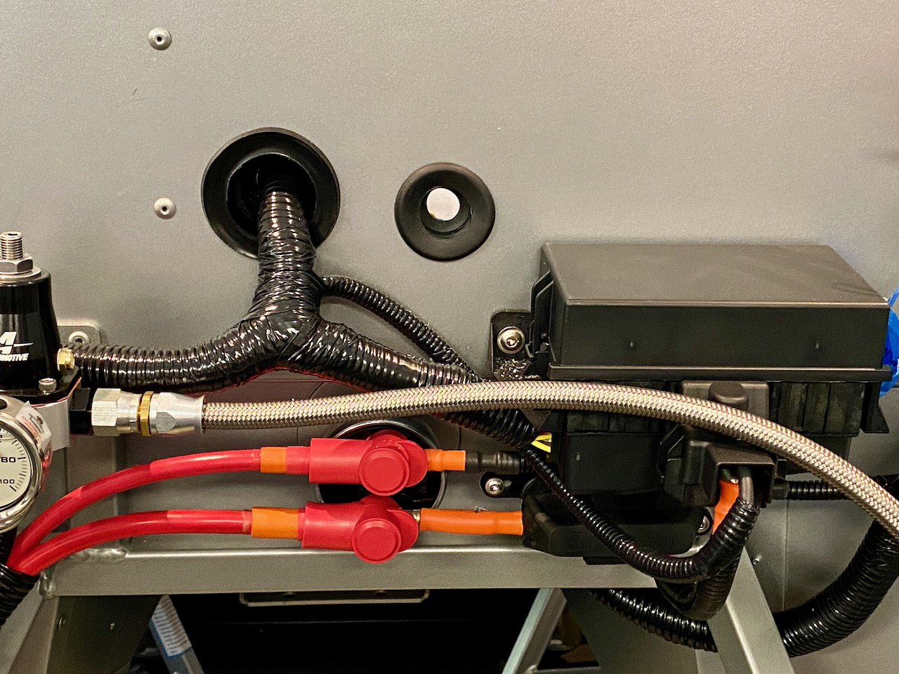
I used a cutoff switch as a distribution point, but took a slightly different approach. I tried to copy Edwardb's approach, which makes sense to me:
Bottom left - 2 ga. wire from battery
Bottom right - outgoing wire (unswitched) to Coyote master fuse and then on to coyote PDB.
Top left - 4 ga. wire (switched) running back to starter
Top right - switched power to bus bar on firewall and RF harness
MkIV Roadster build: Gen 2 Coyote, IRS, TKO600. Ordered 10/24/18. Delivered 1/29/19. Engine installed 8/8/21. First start 9/12/21. First go-kart 9/17/21. Off to paint 4/11/22. Back from paint 12/30/22.
Build thread here.
-
Post Thanks / Like - 1 Thanks, 2 Likes
 Moniz
Moniz thanked for this post
-
25th Anniversary #9772
thanks guys - no cutoff switch in my build but makes sense now - thanks!
-
JohnK explained better than I did and the picture is spot on. Very nice.
-
Post Thanks / Like - 1 Thanks, 1 Likes
JohnK thanked for this post


 Thanks:
  Likes:


 Reply With Quote